Alternator Circuit Explained | Diodes have the property of allowing current to flow in only one direction, while blocking current flow in the other direction. This test will not prove the functionality. See full list on alternatorparts.com An alternator works with the battery to supply electricity to components of a vehicle. The diode trio consists, as the name suggests, of three diodes, one per phase, which provides field current to the alternator regulator.
The regulator uses the control voltage input to control the amount of field current input that is allow to pass through to the rotor winding. B is the alternator output wire that supplies current to the battery. Four wires connect the alternator to the rest of the charging system. The inputs are the field current supply and the control voltage input, and the output is the field current to the rotor. Can i use this alternator?

Once the engine is in the idling mode the dynamo starts getting a field current through the ignition warning lamp. Ig is the ignition input that turns on the alternator/regulator assembly. The bridge rectifier consist of six diodes, one pair for each winding. Because there are three windings, each with a positive and a negative half, by the time the voltage is passed through the diodes, there are six pulsations for each rotation of the rotor. Alternators produce alternating current through a process known as electromagnetism. Diodes have the property of allowing current to flow in only one direction, while blocking current flow in the other direction. At this time, the voltage/current source for the field current is from the battery, through the ignition switch, and through the warning lamp. A voltage regulator converts the power generated by the alternator to direct current. The inputs are the field current supply and the control voltage input, and the output is the field current to the rotor. Four wires connect the alternator to the rest of the charging system. All alternator manufacturers strongly advise not doing this! Mar 29, 2020 · alternators are mounted to the engine and are operated by a serpentine belt or powered by the crankshaft directly. After the engine is started, and the alternator is up to speed, the output of the diode trio is fed back to the regulator, and serves as a source of current for the field current.
An alternator works with the battery to supply electricity to components of a vehicle. This rotor spins past wire coils causing a magnetic field. If the battery voltage drops, the regulator senses this, by means of the connection to the battery, and allows more of the field current input to reach the rotor, which increases the magnetic field strength, which ultimately increases the voltage output of the alternator. Mar 29, 2020 · alternators are mounted to the engine and are operated by a serpentine belt or powered by the crankshaft directly. Today, i will be sharing some basic info about the terminal connections of an alternator with full explanation about its working of it field (rot.

A voltage regulator converts the power generated by the alternator to direct current. This rotor spins past wire coils causing a magnetic field. See full list on alternatorparts.com Alternators produce alternating current through a process known as electromagnetism. Four wires connect the alternator to the rest of the charging system. How do you wire a single wire alternator? It consists of guidelines and diagrams for various types of wiring strategies and other products like lights, home windows, etc. An alternator works with the battery to supply electricity to components of a vehicle. Critical components, such as radios, have their own intern. When you first get in the car and turn the key on, the engine is not running and the alternator is not spinning. This is close enough to d/c for most automotive components. See full list on alternatorparts.com All alternator manufacturers strongly advise not doing this!
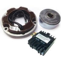
This rotor spins past wire coils causing a magnetic field. More images for alternator circuit explained » Diodes have the property of allowing current to flow in only one direction, while blocking current flow in the other direction. Ig is the ignition input that turns on the alternator/regulator assembly. See full list on alternatorparts.com
At this time, the voltage/current source for the field current is from the battery, through the ignition switch, and through the warning lamp. It consists of guidelines and diagrams for various types of wiring strategies and other products like lights, home windows, etc. One of the pair is for the negative half cycle, and the other for the positive half cycle. The headlights, dashboard lights, radio and interior lights all rely on the alternator to keep the battery charged and the car operating. S is used by the regulator to monitor charging voltage at the battery. See full list on alternatorparts.com The alternator has a rotor that spins when the engine cranks. The inputs are the field current supply and the control voltage input, and the output is the field current to the rotor. This conversion to d/c takes place in the bridge rectifier. The regulator has two inputs and one output. A/c voltage is of little use in a d/c system, such as used in an automobile, so it has to be converted to d/c before it can be used. The bridge rectifier consist of six diodes, one pair for each winding. Diodes have the property of allowing current to flow in only one direction, while blocking current flow in the other direction.
Alternator Circuit Explained: The headlights, dashboard lights, radio and interior lights all rely on the alternator to keep the battery charged and the car operating.

comment 0 Post a Comment
more_vert